Please note: Electricity: The spark of life ended in April 2019. To find out what exhibitions and activities are open today, visit our What’s On section.
I’m an asset data manager for Electricity North West, and I’ve worked closely with the Science and Industry Museum and with artists Tekja on the Electricity: the spark of life exhibit.
When we found out that the museum was hosting an electricity exhibit, we knew we needed to be involved. We operate the electricity network in the North West—the clue’s in our name, really.
We operate almost 13,000 km of overhead lines, and 45,000 km of underground cables from Macclesfield to Carlisle. And we monitor electricity usage across the region so we know where investment is needed to keep people’s lives running.
We invest almost half a million pounds in the North West every single week.
Now, if you really want to be in the know, there are a few of things you should understand about some of our terminology and how we work.

Science Museum Group © The Board of Trustees of the Science Museum
Firstly, our underground network is always referred to as ‘cables’ and our overhead network is always referred to as ‘lines’, which helps us distinguish between the two. So we have people who are trained as cable jointers (who only work on the underground network) and people who are trained as overhead line workers (who only work on overhead lines). We also have ‘fitters’ who work in our substations. A ‘circuit’ can refer to either underground cables or overhead lines.
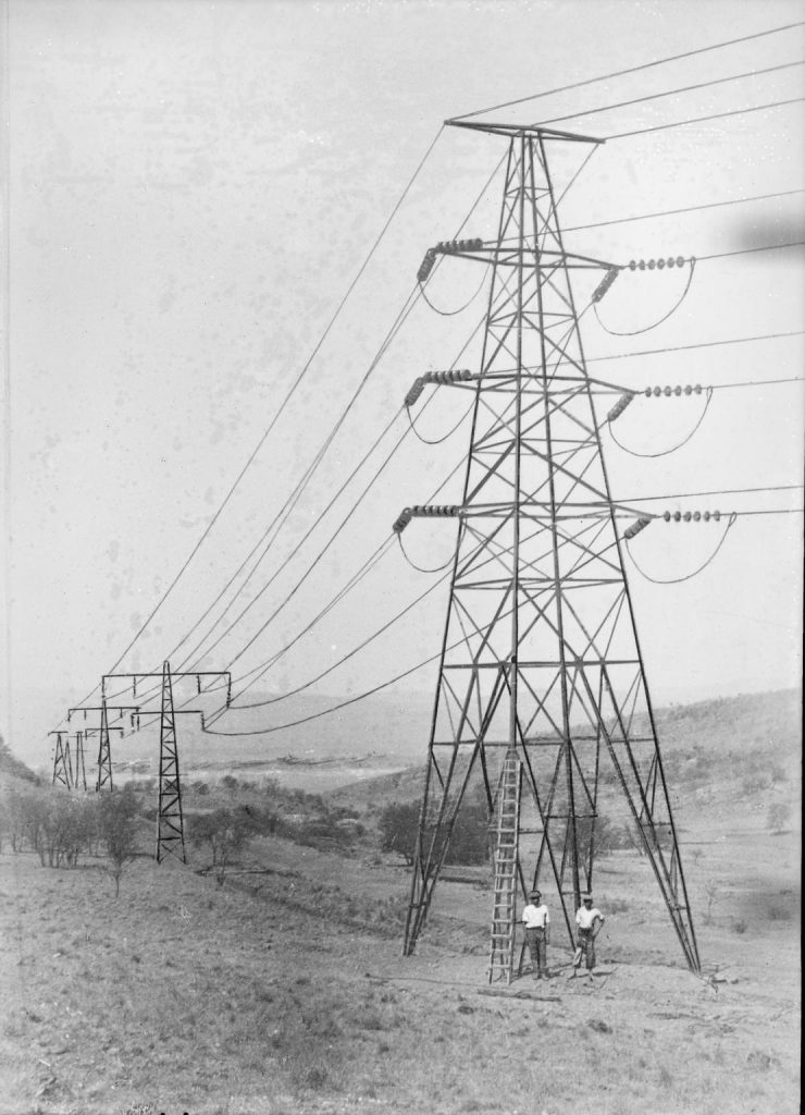
The second thing that you should know, is that our overhead network is supported by wooden poles (definitely not ‘telegraph poles’, as telegraph poles only carry phone lines), or by what we at Electricity North West would call ‘steel lattice towers’.
When I joined Electricity North West, one of the first things I learned was that what I’d thought of as ‘pylons’ are actually referred to in the industry as ‘towers’, or to use the full name, steel lattice towers. Calling them pylons in our line of work is a major faux pas!
So why do we not call them pylons like everyone else? Well, within engineering, the term ‘pylon’ tends to refer to a solid structure that suspends something from another structure. For example, the bit that suspends the engine from an aircraft wing is a pylon.
Science Museum Group © The Board of Trustees of the Science Museum
The steel tower is the entire structure, and arguably the pylon would be the part of the structure that the insulators and lines are suspended from. On the other hand, it could just be a trick to catch out the uninitiated!
If you look at the Flow installation within the Electricity: The spark of life exhibition, you might spot the term ‘tower circuit’ on the schematic diagrams. This refers to a line suspended from steel towers. Definitely not pylons…
The final thing you might notice is that there are often some letters on our diagrams next to tower lines. Most of our towers carry two circuits (one of each side). Each circuit is a set of three wires, and the circuits on a tower might go to different places and are controlled by different switches.
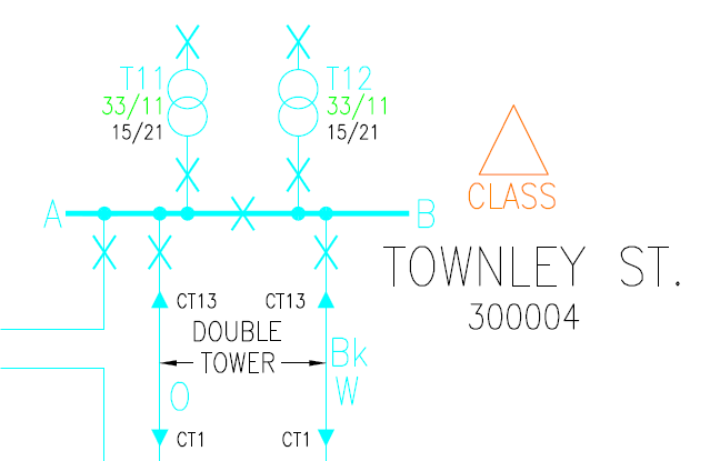
Image credit: Dan Wilson
When we need to do some work on a tower, our overhead lines workers need to know which side of the tower they should be working on, and more importantly, which side is turned off so is safe to access.
The letters on the diagram give a colour code (for example, O is Orange, Bk is Black and W is White), which is also shown on the tower itself, and helps our line workers identify which circuit is which, and we also have coloured flags which fit into specially shaped sockets at the base of the tower as a second check.
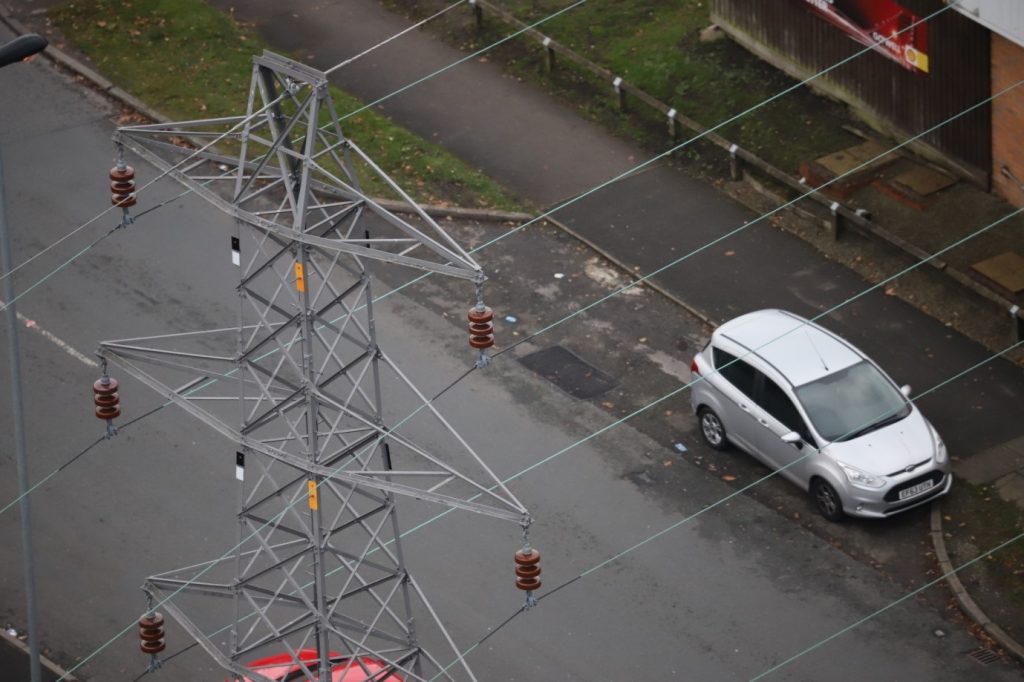
Image credit: Dan Wilson
If you look carefully when you are out and about, you might be able see the colour plates on the towers themselves – there are usually three on each side of the tower.